Troyster510
-
Posts
24 -
Joined
-
Last visited
Content Type
Profiles
Forums
Articles
News for Home Inspectors
Blogs
Gallery
Store
Downloads
Everything posted by Troyster510
-
High temp orange stranded wire.

-
-
-
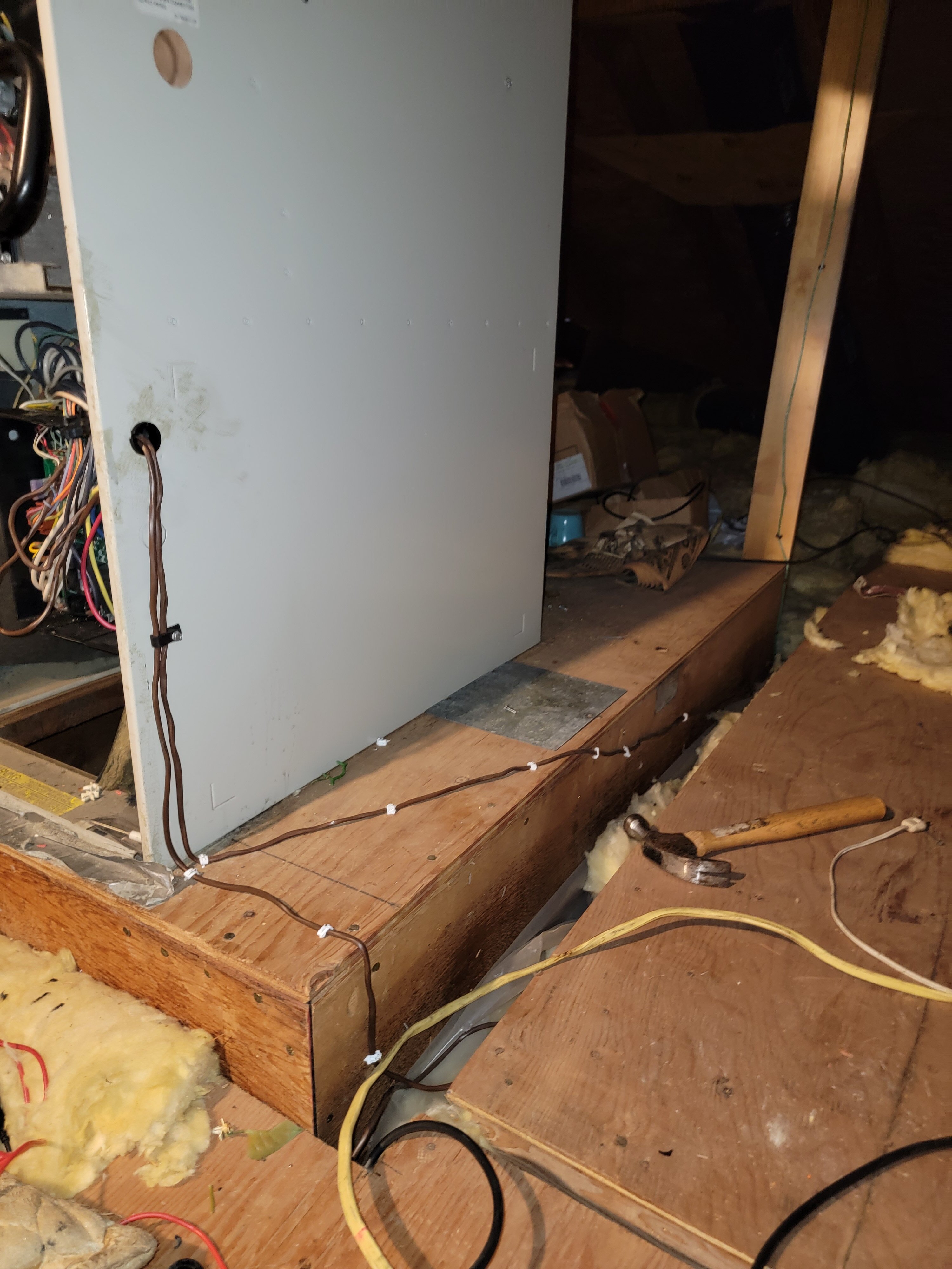
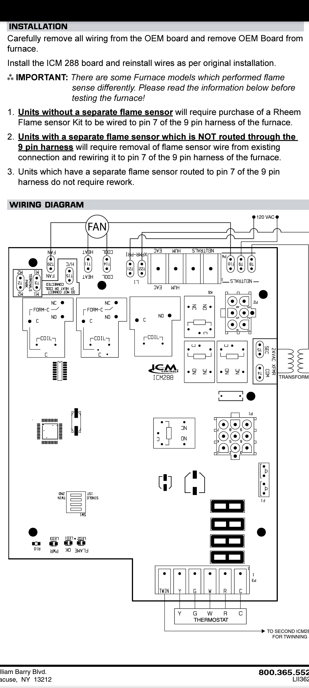
I have the heater running in a temporary way at the moment. One thing that threw me off was that the igniter and flame sensor both share the same neutral wire. When I was trying to get a micro amps reading I had no idea that all the amps were basically being grounded out by the neutral wire. As a temporary test only fix, I ran a wire from the flame sensor directly to pin 7 in the 9 pin harness. I saw the orange light light up to let me know the board detected a flame and the burners remained on. I was pretty relieved. I'll send an update with photos once I have the fix permanent.
-
I'm only moving that one. I was also testing micro amps on the flame sensor. I couldn't get a decent reading while it was inside the furnace, but while testing it over a stove burner I got 3.5 micro amps. I cleaned it up, but I still wasn't getting a good reading when mounted in the furnace. I decided to purchase a new one just to play it safe. The wire has continuity.
-
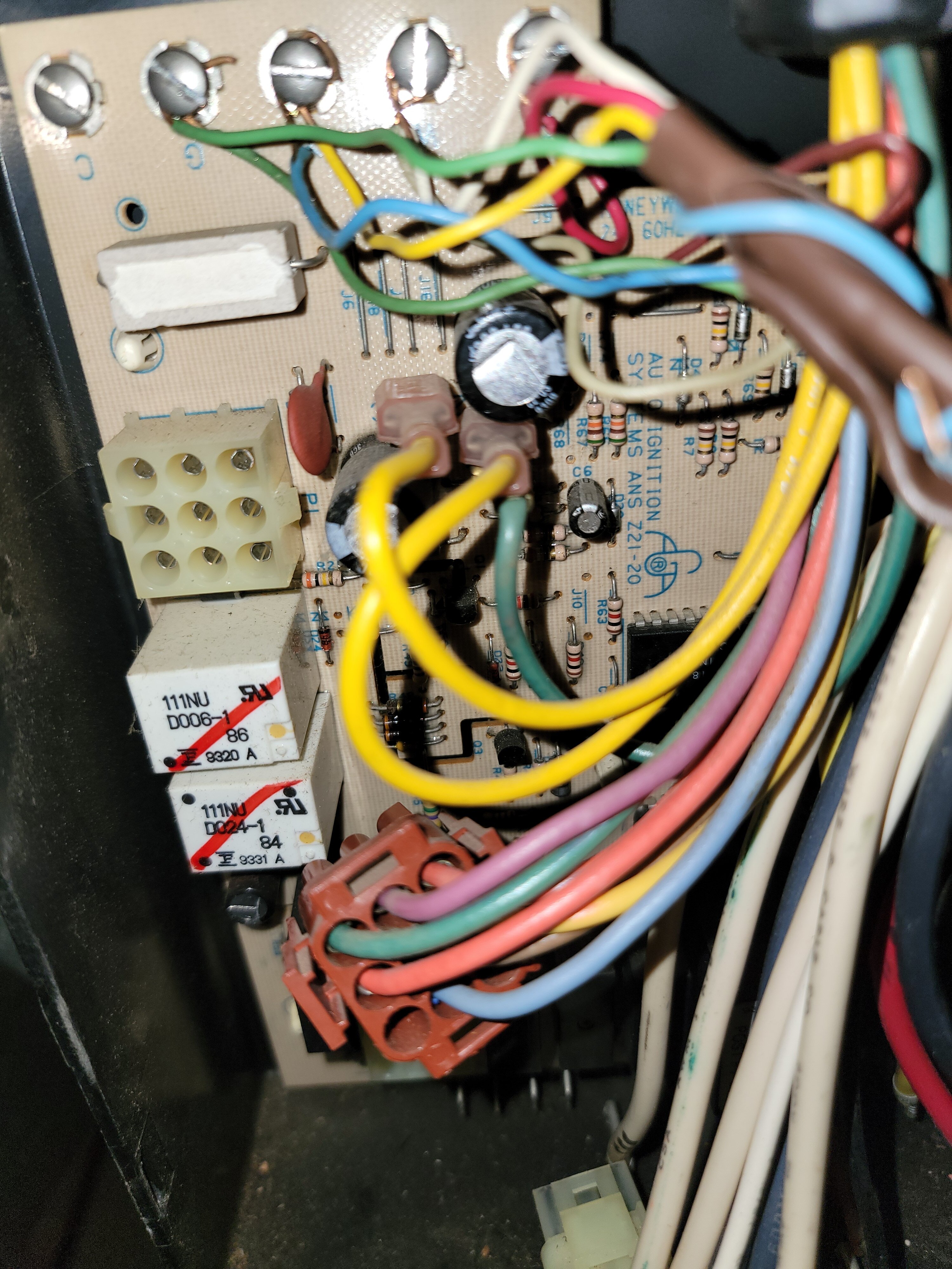
I take that back. After looking over everything more carefully it looks like I need to move pin 3 wire in p2 (6 pin harness) and move it to pin 7 hole in p1 (9 pin harness). I may need a Molex extraction tool. I've tried using tiny wires with no success.
-
On a spot marked m1.
-
Looks like there's a modification required. According to this diagram the flame sensor wire needs to be moved from its previously designated spot over to pin 7.
-
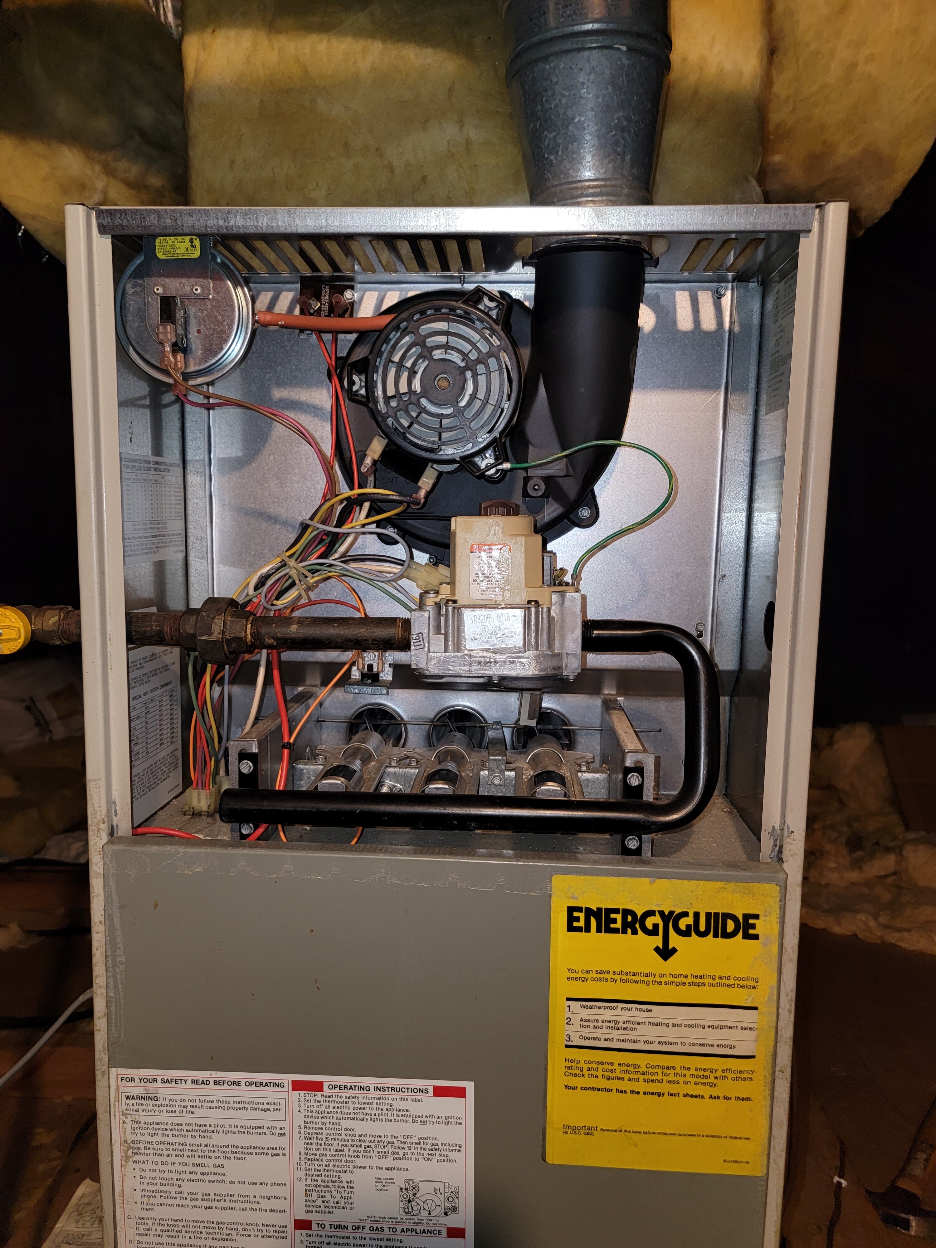
I completely installed the new board. It mostly works. The igniter starts the burners (which is something the old board wasn't doing anymore), but as soon as the igniter shuts off, the burners shut off too. I've tried cleaning the flame sensor, but that had no positive effect. The flame sensor looked fairly clean anyway. At this point I'll need to hook the flame sensor up to a meter to see if it's generating current. I've already checked the continuity of the flame sensor wire. I have the wire connected to M1 on the board.
-
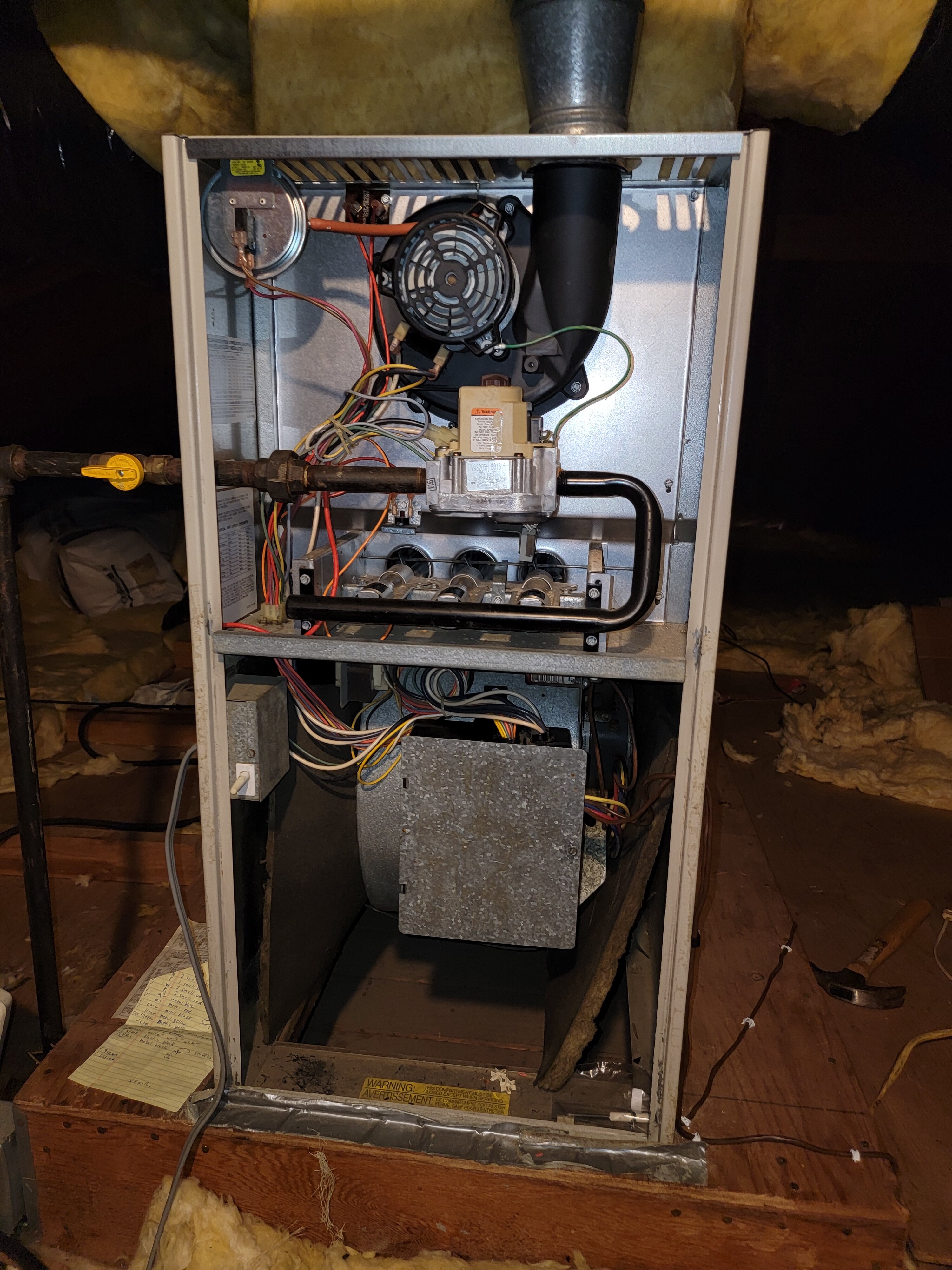
I put the new control board in today. Cleaned everything up while I was at it. I'm going to wire it up later, maybe tomorrow or Tuesday.
-
With electric heaters. I live in California, so it's no emergency.
-
The control board went back to being available on Amazon again, so I purchased it. ETA is 11/28 - 12/2.
-
I should Probably mention why I thought that "low cost replacement board" might be compatible. It reads replacement for Rheem 62-24084-82. Well I read somewhere else that the 62-24084-82 was the replacement for my 62-22737-08. It seemed weird that I couldn't find anything relating the "low cost replacement board" directly with my 62-22737-08 board, but then thought maybe because my 62-22737-08 board is so old and already replaced by the 62-24084-82. When I look at the photo of the "low cost replacement board", it has all the connections I need. At least it appears that it does. Anyway, just wanted to mention that just in case that makes a difference.
-
Yes, I'd appreciate that, thank you.
-
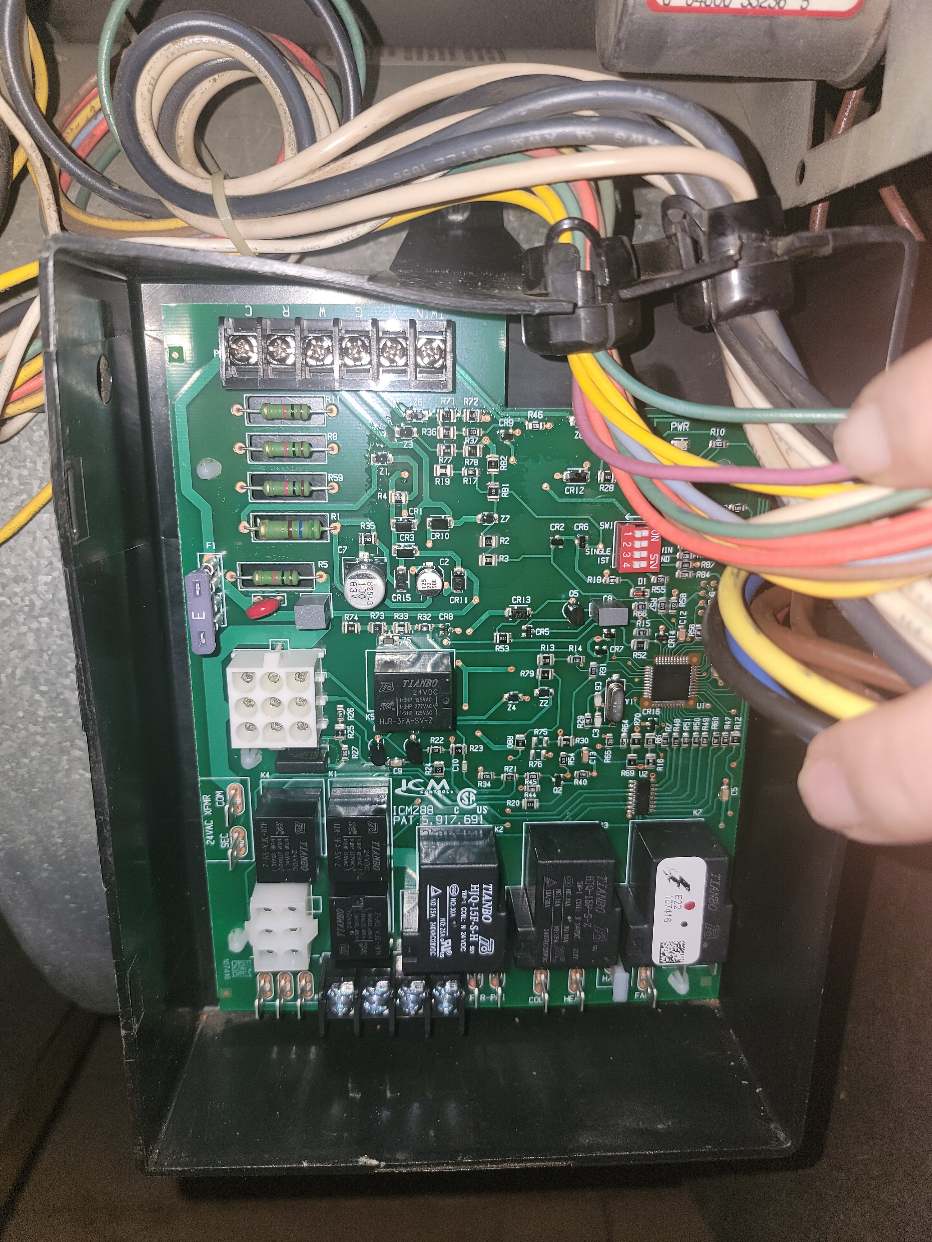
Marc, The product on the link you sent me is no longer available. I found this one. I think it's probably compatible. ICM Controls ICM288 Furnace Control, Low Cost Replacement for Rheem 62-24084-82 Control Boards https://a.co/d/aOV65Uq
-
So if the old board says 24vac and the new card says SEC, which is also 24vac (secondary winding) then it seems like that's the correct place for it. The outlet the furnace plugs into hasn't been changed, so I'm sure the hot and neutral are on the correct sides, but I know how to test for that. Thanks for the heads up.
-
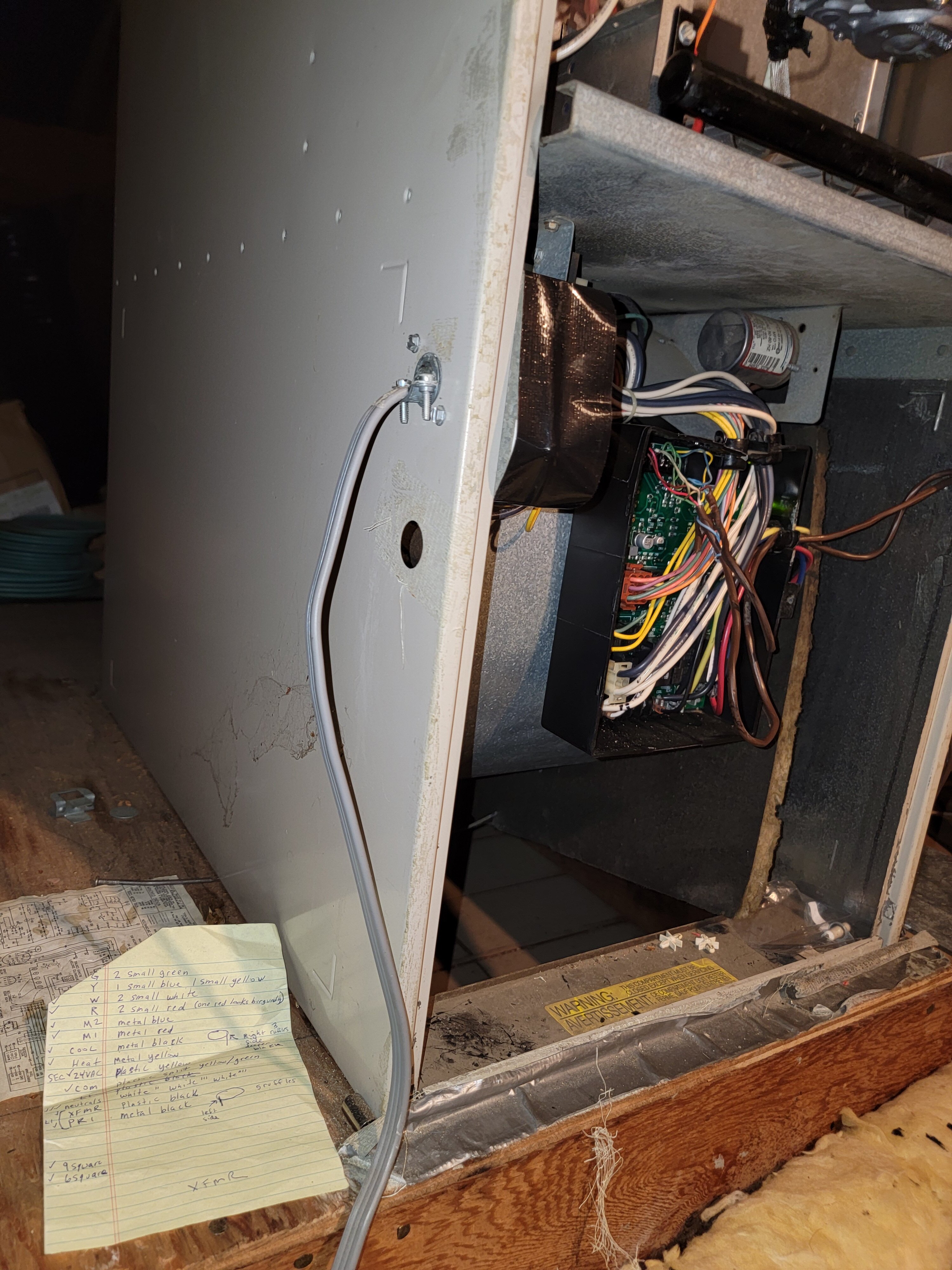
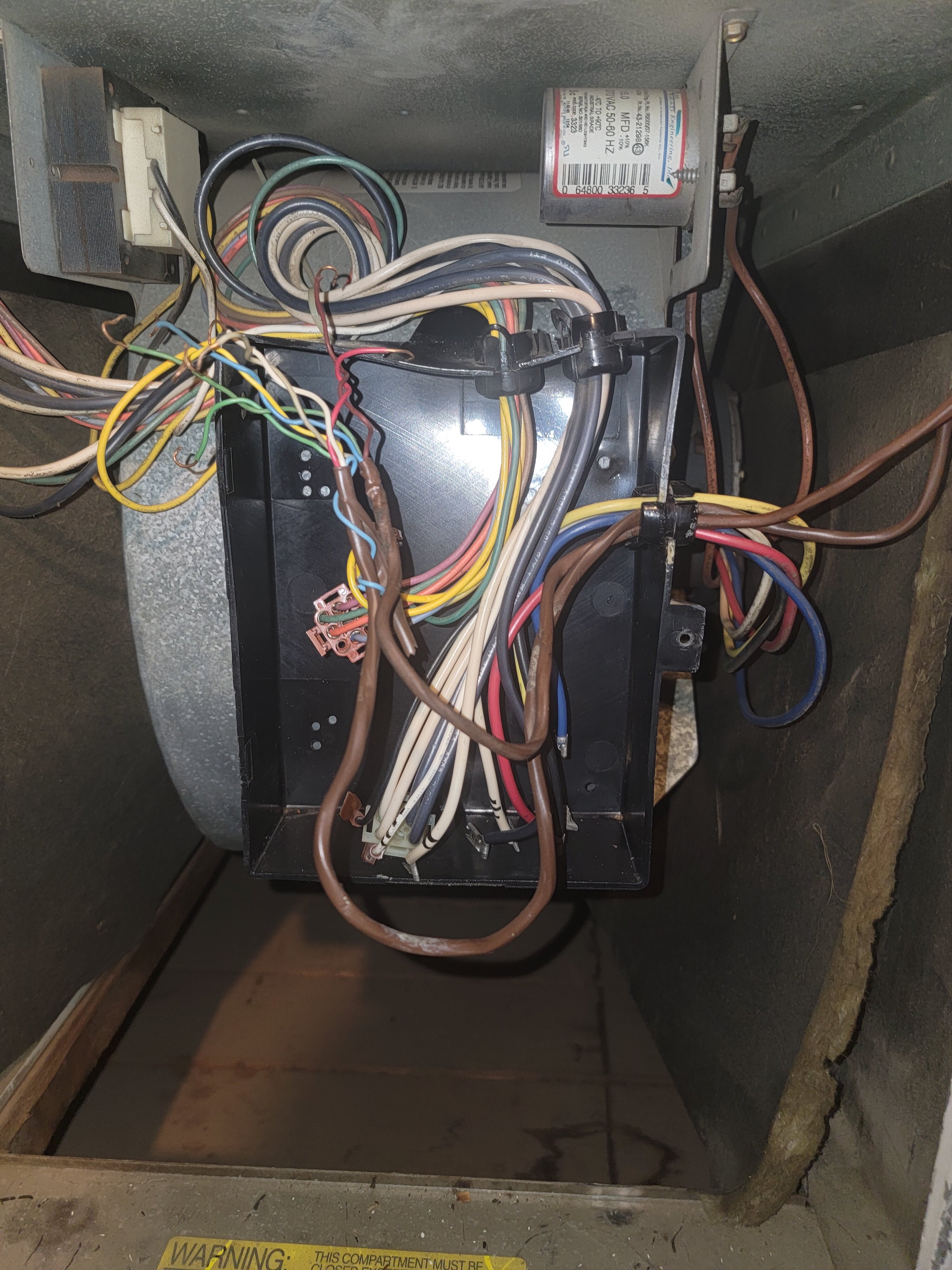
I think all the small wires will be consistent because I'm just moving them from one board to the other board. I'm just going to make sure the colors are under the same letter screw. I'll definitely send you a photo first though. The wires I'm asking about are the bigger yellow wires. On the old board the thick yellow wire has a thick green wire with it and it's connected to a screw labeled COM. Right next to that (also on the old board) is another thick yellow wire that connects to a screw labeled 24VAC. Those 2 wires are my primary focus. On the new card, the only remaining screws that appear to be the equivalent place to put those 2 wires are on a set of screws designated as 24VAC XFMR. In that section, one screw is labeled COM and the other one is labeled SEC. It makes sense to me that the thick Yellow and Green from COM on old board will go to COM on new board and that the thick single Yellow wire from 24VAC on old board will go to SEC on new board. I'm just trying to clearly understand where their new homes are.
-
On my board there's a COM and 24VAC. The COM is the green and yellow wire plug, and the 24VAC is the yellow wire plug next to it. On the new board there is a COM and a SEC, both in a section designated as 24VAC XFMR. I'm assuming that the green and yellow wire plug goes to COM (just like the old board) and the yellow wire plug goes to SEC. Am I correct?
-
Thank you very much for the link and information. I noticed that the new card has a different layout for the wires. Are all the labels on the board pretty standard? I want to make sure I have a correct place for all those wires and plugs. I suppose I can compare the Amazon image with my board.
-
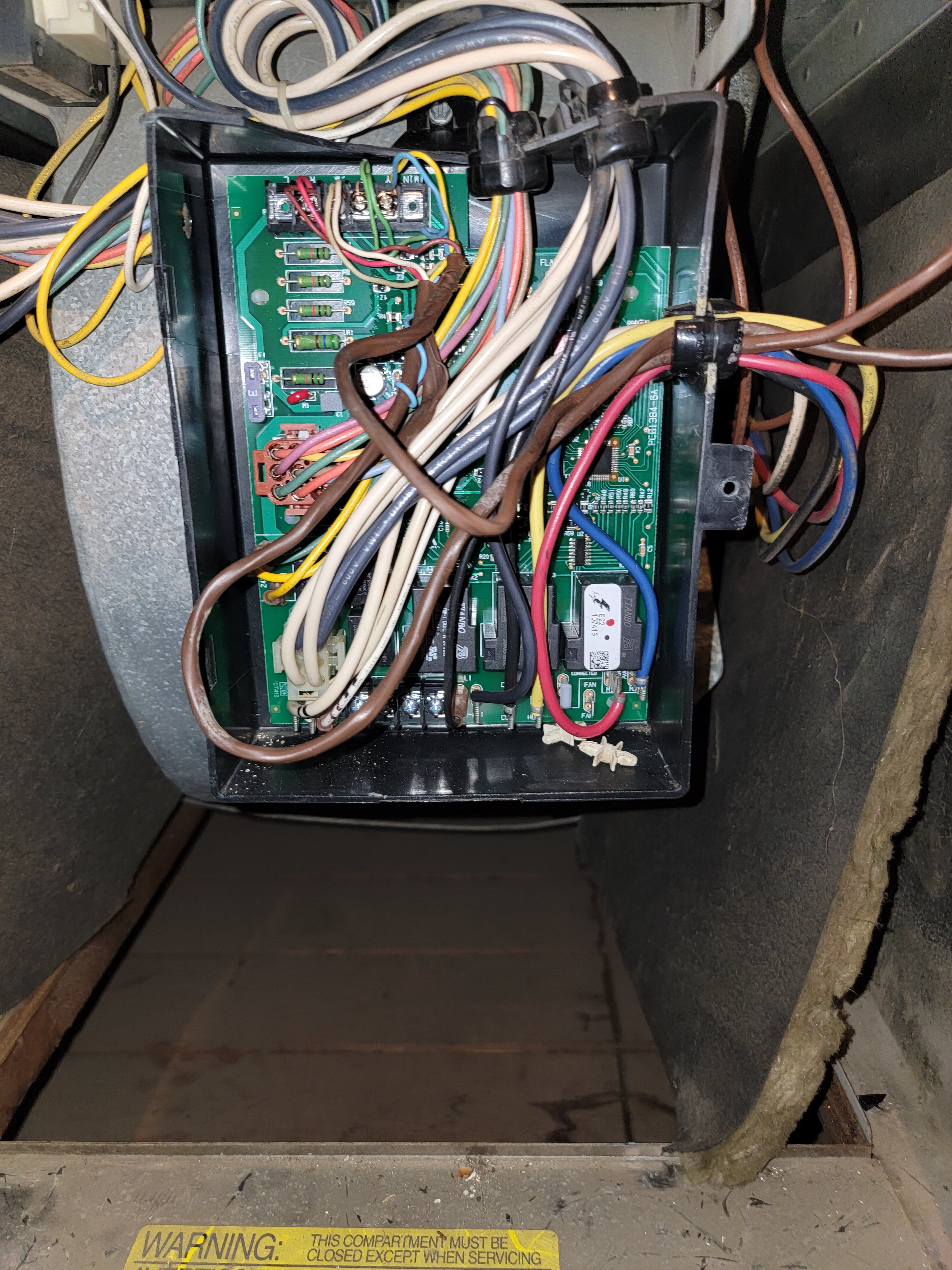
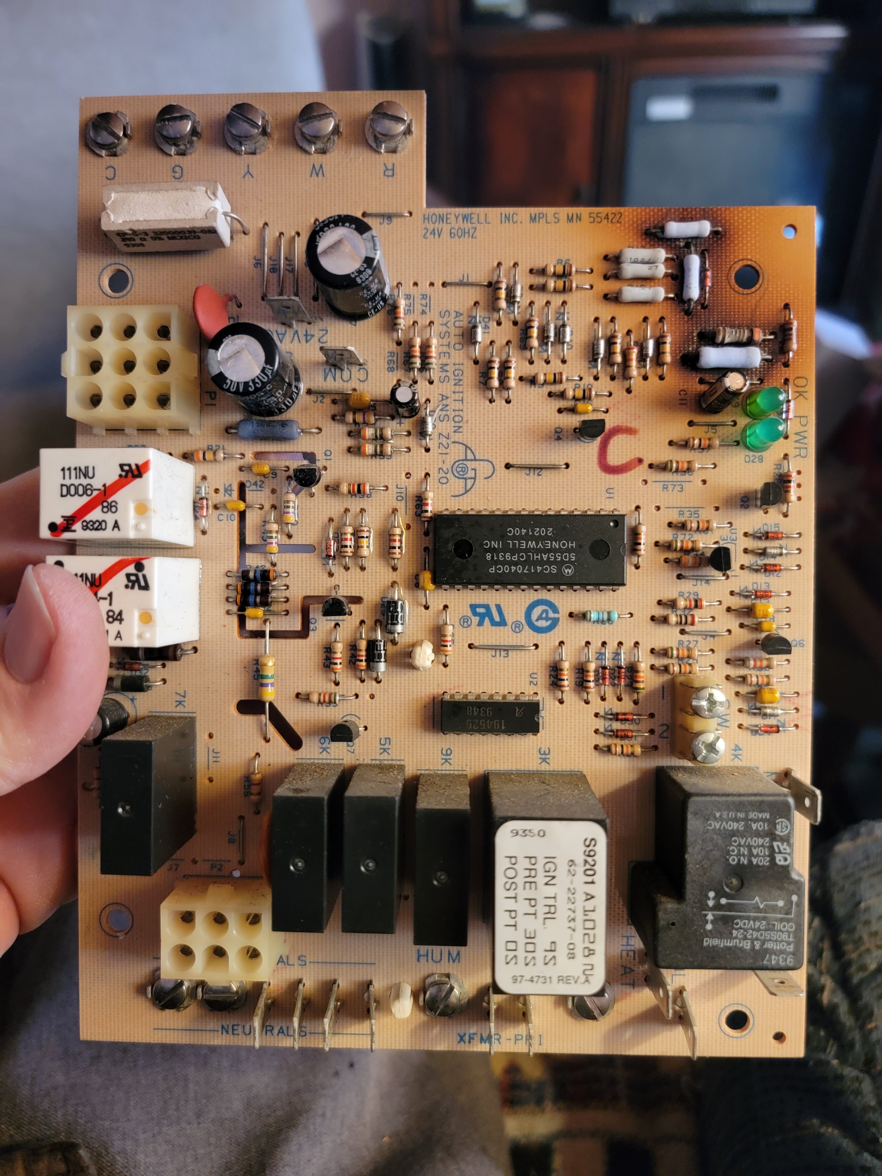
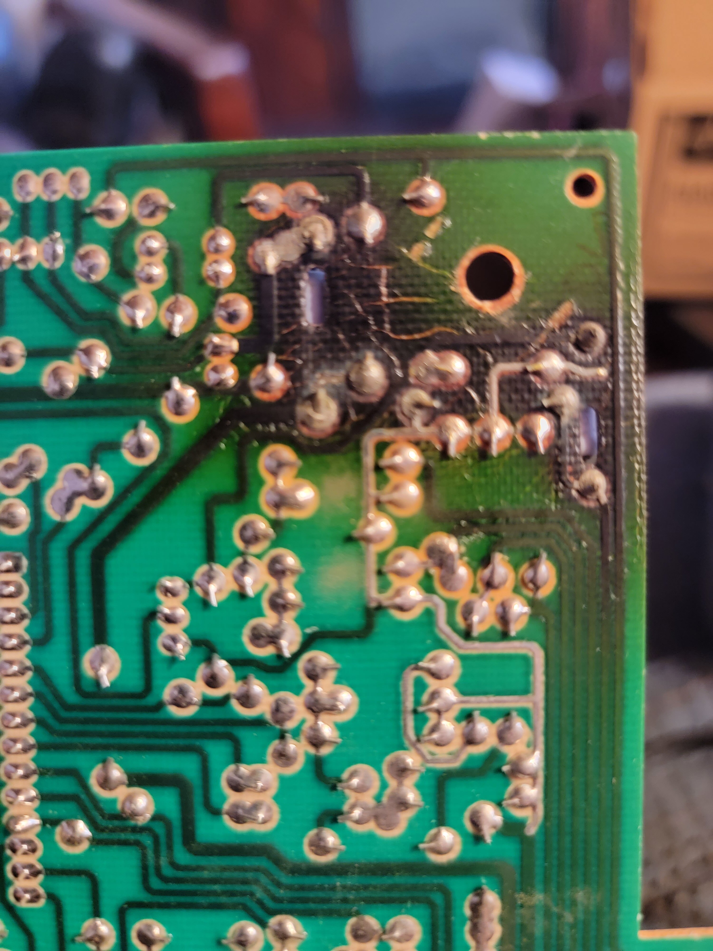
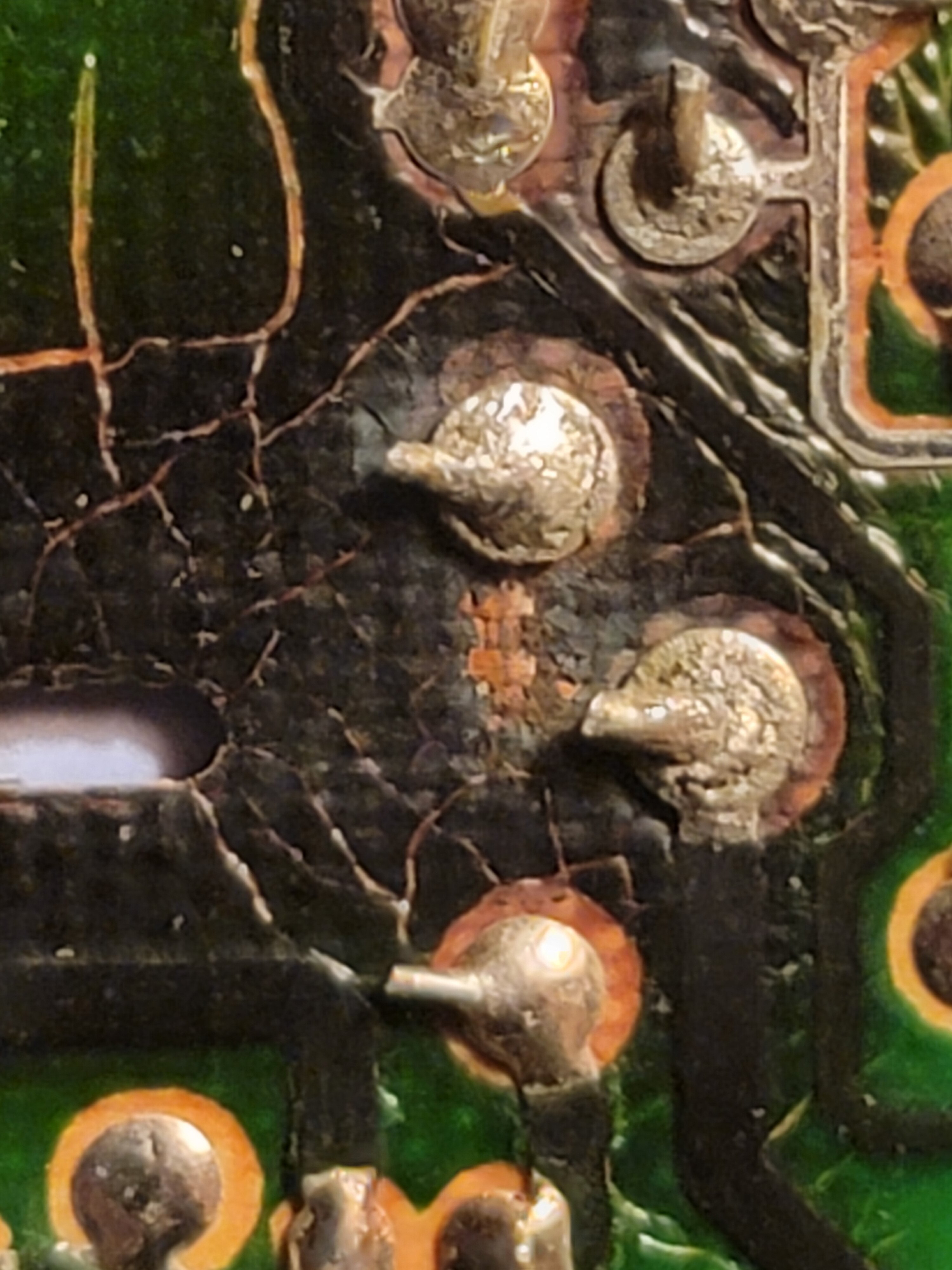
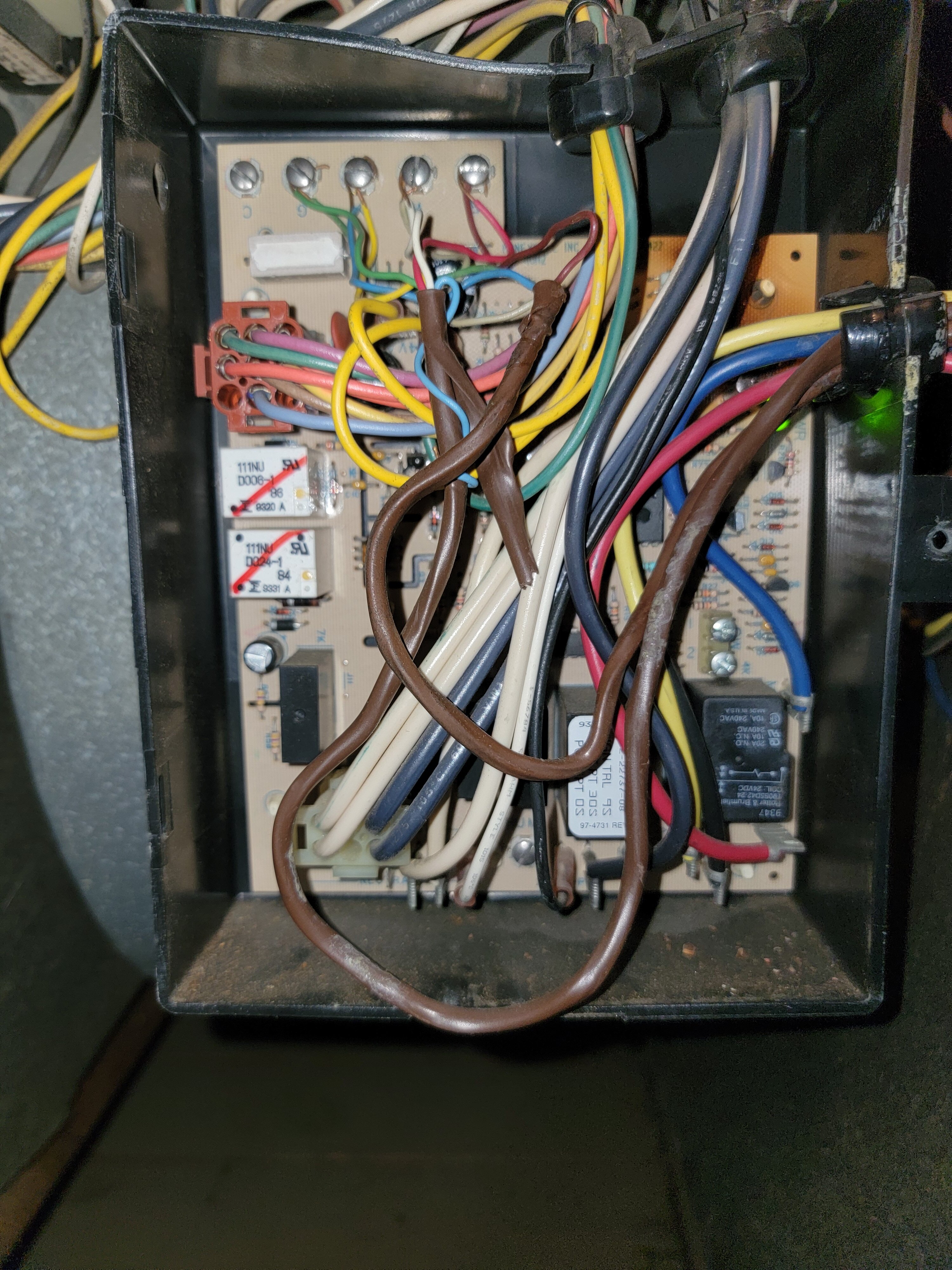
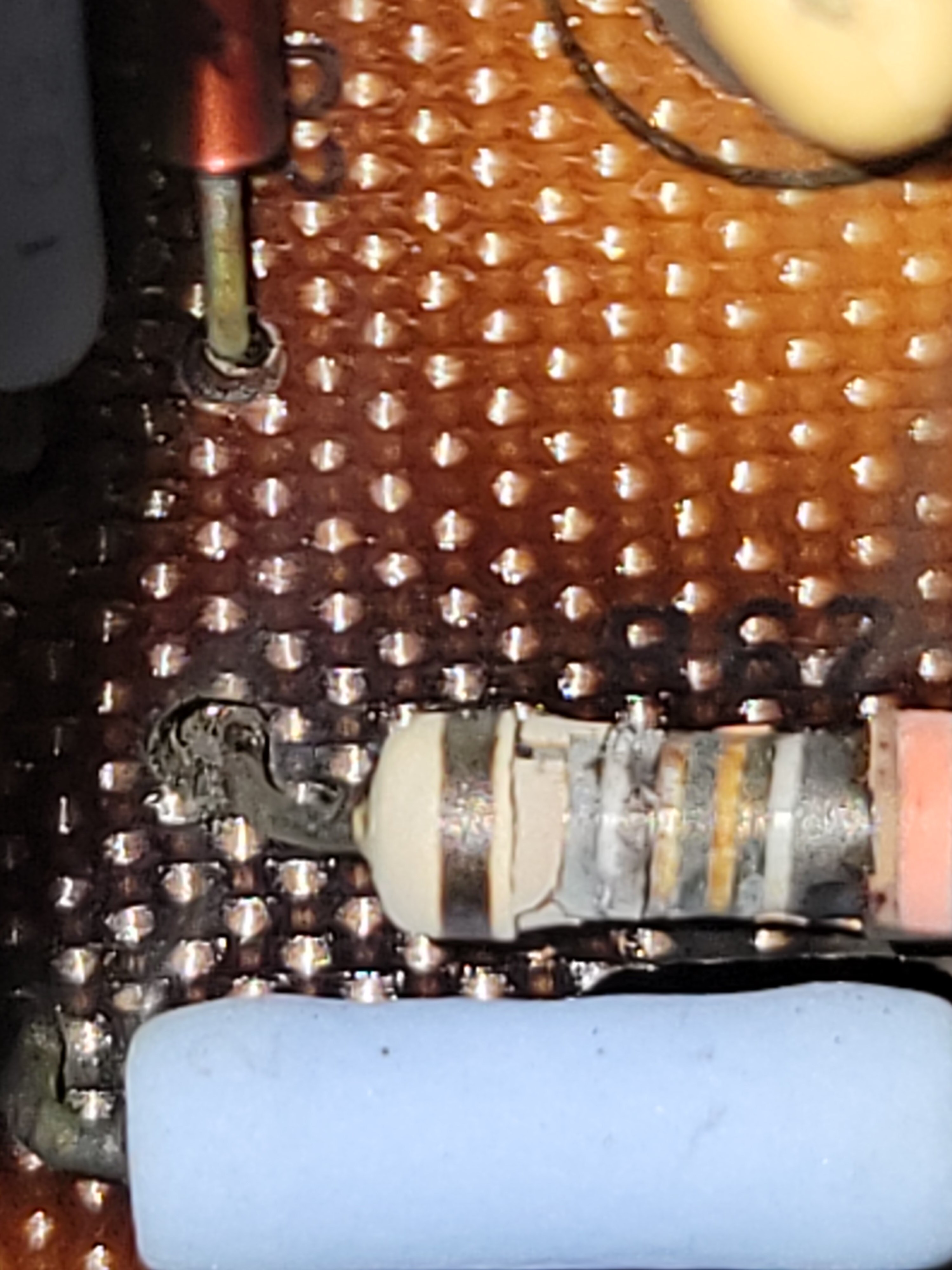
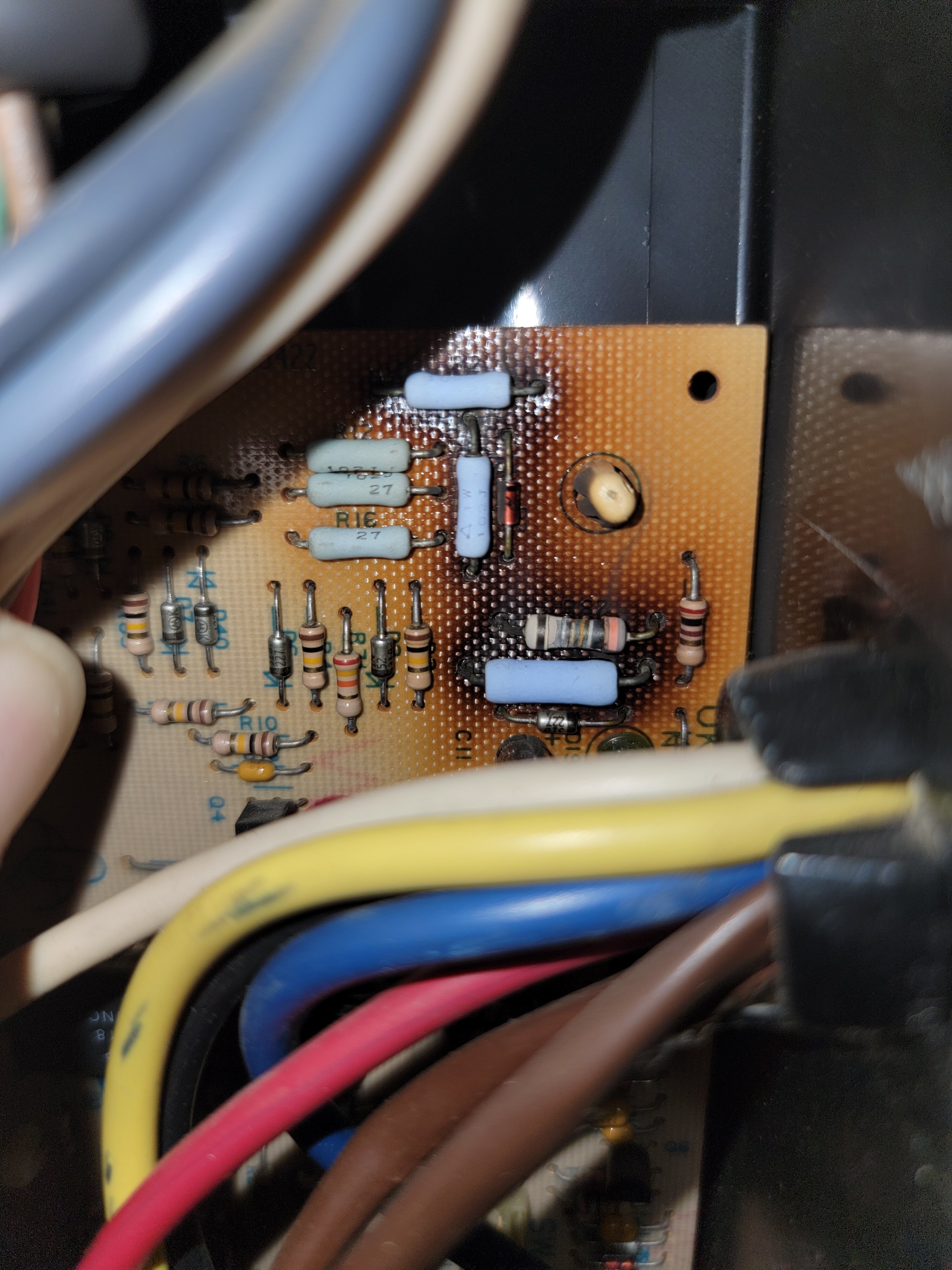
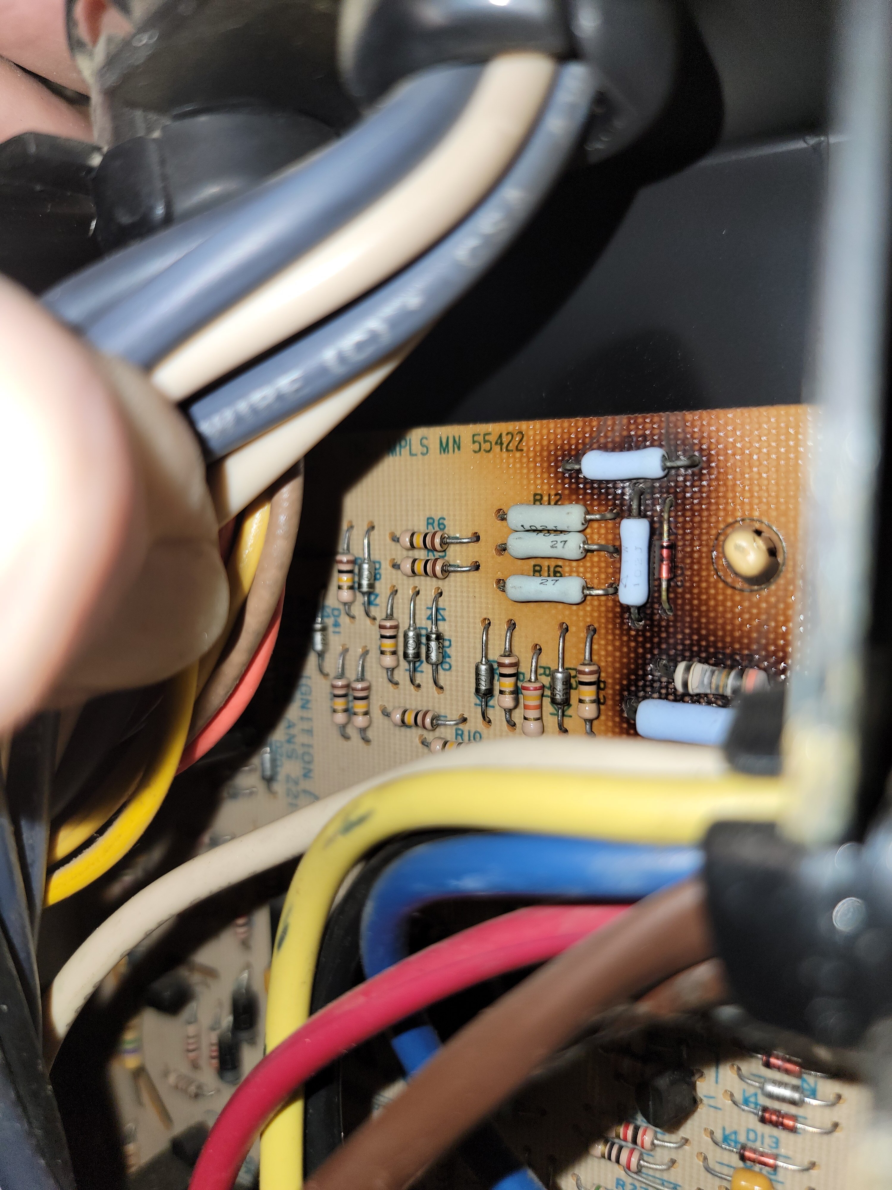
62-22737-08 On the back of the card it looks like a copper strip may have come off the board. My ohm meter can't track where the resistor goes on one leg and I see something suspicious looking on the board. This is also at the worst looking resistor, so if the board was damaged that's likely to be the spot. In the last image you can see an 'L' shaped piece on the board. It looks like a copper strip is missing there. I would love to see the front and back of a good board.
-
This is the way the back of the board looks and I believe I found the part number too.
-
Yep, been there, done that. I made a point to get a whole photo to have before removing the wires. Once I remove the wires I should be able to find the part number information a lot easier. At that point I'll have a far better idea about the overall damage. Thanks for the help and information, I'll keep you posted.
-
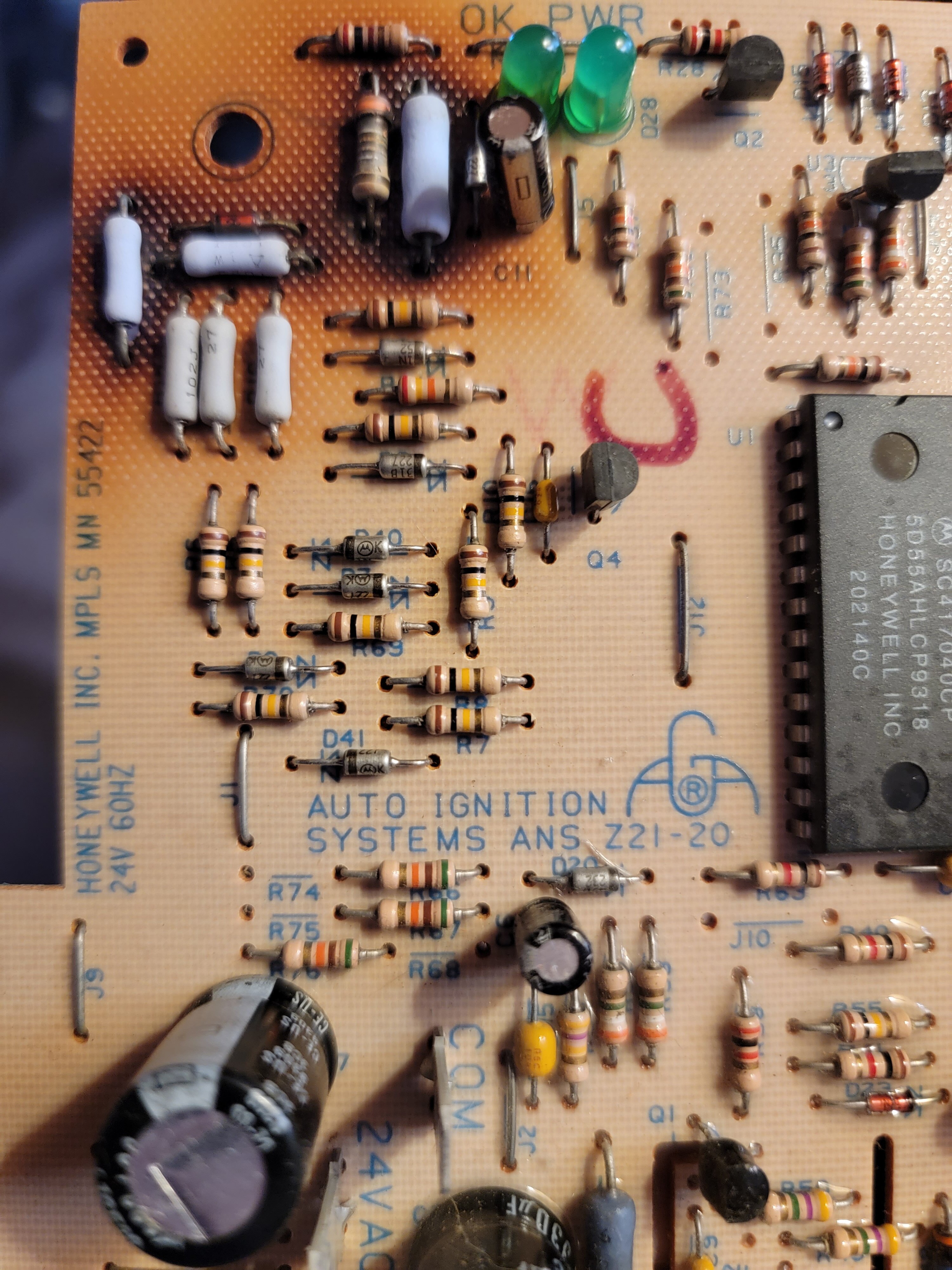
The resister with the stripes does appear burned up. I haven't taken the board out to test it yet. The burners won't start. The igniter works but the automatic gas valve only gets 10 volts of power for maybe half a second. I figured the board was a likely candidate.
-
I have a Rheem Criterion furnace with what appears to be the exact same control board. Like yours, my board is burnt around the same resistors. Do you by chance know the part number or have a wiring diagram for that board?