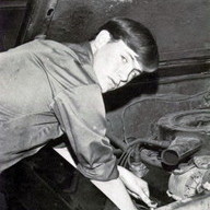
John Dirks Jr Posted September 7, 2007 Report Share Posted September 7, 2007 The house had a major addition put on in 91 where additional HVAC equipment was added. I found this was done to wire it up. First of all there was a second SE cable and I am not sure where it came from. It went into a main shut off panel with a 125A breaker that was being used as a sub panel for the added HVAC. SE cable came back out of this shut off and went across the room overhead to a second main shut off panel that was being used as a junction box to splice the SE cable to the feed line for the added HVAC. That wiring went into conduit into the air handler. I suppose it traveled through duct work to the other unit. You can see in the picture the cover I am holding up. There was no breaker in this panel so the hole was open. You can see the SE spliced to the feed and wrapped with electrical tape. That smaller feed wire is being protected by a 125A breaker which is too big for that wire, not to mention the splices. All messed up.... Image Insert: 131.74 KB Quote Link to comment Share on other sites More sharing options...
hausdok Posted September 7, 2007 Report Share Posted September 7, 2007 Originally posted by AHI The house had a major addition put on in 91 where additional HVAC equipment was added. I found this was done to wire it up. First of all there was a second SE cable and I am not sure where it came from. It went into a main shut off panel with a 125A breaker that was being used as a sub panel for the added HVAC. OK, You're confusing the hell out of me. Stop calling them mains. Anything past the service disconnect is a sub-panel. Lock that into your head and don't let it go. What do you mean by additional HVAC system; are you talking about a second furnace, heat pump, AC, what? Where do you see a second "SE" as you call it? Besides, stop calling it an SE - if it is not a service entrance. If it feeding a sub-panel - it's a feeder cable. SE cable came back out of this shut off and went across the room overhead to a second main shut off panel that was being used as a junction box to splice the SE cable to the feed line for the added HVAC. No, a "feeder" came out of the sub-panel and into the enclosure for a disconnect, which, if I'm understanding what you're trying to say, is the one pictured. Because an addition has been added, the enclosure is no longer a disconnect and has been turned into a junction box for an extension of the feeder. However, it looks like that feeder is now powering two separate feeders. Where do these go? Does each feed a separate device or do they both feed the same device? If separate devices; obviously there should be a properly-sized disconnect within sight of each. If that enclosure is within sight of each (and it isn't according to your description) what's missing in that enclosure is the hot bus and breakers. If it's just a junction box for some splices, I don't think breakers would be necessary That wiring went into conduit into the air handler. I suppose it traveled through duct work to the other unit.I can't envision this. I've tried, believe me. You can see in the picture the cover I am holding up. There was no breaker in this panel so the hole was open. You can see the SE spliced to the feed and wrapped with electrical tape. That smaller feed wire is being protected by a 125A breaker which is too big for that wire, not to mention the splices. All messed up....So the hole was open but there's a cover on the panel and the splices are fully insulated with tape. Right? How do you know that the splice can't handle a 125 amp load if you can't see it. If this is merely a junction box I don't see this as an issue. It would be better if the cover was secured with screws to keep folks out, but the main thing is that there's a cover. Apparently the power from that feeder is being fed to two different devices. Either that, or it's powering one device through a total of 4 conductors, which would be pretty bizarre. Although,.........if that's the case (which I hope it isn't) is it really over-fused if the two cables together are equal to or larger in diameter than a single cable of the proper gauge? If it's feeding two devices and the load on the feeder from one device doesn't exceed the rating for the feeder and the combined load for the two doesn't exceed 125amps, and the intent is to shut down the entire HVAC system with one throw, is it really wrong? Assuming that, "Additional HVAC equipment was added," means a second heat pump and there's a disconnect within sight of each pump, I don't see the issue. Your description really has me all turned around. Now, don't get upset if I've got this backasswards, 'cuz it was you who confused me with what seems to be some incorrect terminology and electricity isn't my forte. That's why I've got Jim Katen on this forum as the moderator. Image Insert: 131.74 KB ONE TEAM - ONE FIGHT!!! Mike Quote Link to comment Share on other sites More sharing options...
John Dirks Jr Posted September 7, 2007 Author Report Share Posted September 7, 2007 Sorry about the confusion. I said SE cable since it was that size that is typically used for that. It was 4/0 aluminum feeder then. Sub(not a main, sorry again) on the other wall with 125a breaker feeding the junction box in the picture. Yes it was powering multiple units. I was mainly concerned about the splices and the lack of a separate breaker for each feed. For instance. That was #4 or #3 at best copper wire(the smaller wire in the photo). The only breaker up line from this point is a 125a which is too large for #3 or 4 copper. So yes, this picture shows this box being used as a junction for splices between a single 4/0 al and the two smaller feeds. Now, shouldnt this junction be converted to a sub with a correct size breaker for each of the smaller feeds? This box was mounted directly on the air handler in the utility room. There was another air handler in a crawl at the other end of the property. See the blue collar in the box where the wires go in? That is a conduit that passes directly through the center of the air handler. This job was a short version walk through. One hour of verbal information was the only intent. I spent too much time on the exterior since it was in bad shape. My time was already exhausted by the time I got to this area so I did not go to any extent to trace exactly where every wire went. I just thought this setup didnt look quite right. I know I am stumbling, I admit it. You can bet I will get back up run every time. Thanks for correcting me, or at least attempting to. Quote Link to comment Share on other sites More sharing options...


Recommended Posts
Join the conversation
You can post now and register later. If you have an account, sign in now to post with your account.